How to Calculate Speed and Feed for Milling
Understanding Speeds and Feed Rates
NOTE: This article covers speeds and feed rates for milling tools, as opposed toturning tools.
Before using a cutting tool, it is necessary to understand tool cutting speeds and feed rates, more often referred to as "speeds and feeds." Speeds and feeds are the cutting variables used in every milling operation and vary for each tool based on cutter diameter, operation, material, etc. Understanding the right speeds and feeds for your tool and operation before you start machining is critical.
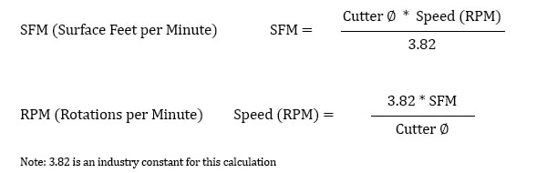
It is first necessary to define each of these factors. Cutting speed, also referred to as surface speed, is the difference in speed between the tool and the workpiece, expressed in units of distance over time known as SFM (surface feet per minute). SFM is based on the various properties of the given material. Speed, referred to as Rotations Per Minute (RPM) is based off of the SFM and the cutting tool's diameter.

While speeds and feeds are common terms used in the programming of the cutter, the ideal running parameters are also influenced by other variables. The speed of the cutter is used in the calculation of the cutter's feed rate, measured in Inches Per Minute (IPM). The other part of the equation is the chip load. It is important to note that chip load per tooth and chip load per tool are different:
- Chip load per tooth is the appropriate amount of material that one cutting edge of the tool should remove in a single revolution. This is measured in Inches Per Tooth (IPT).
- Chip load per tool is the appropriate amount of material removed by all cutting edges on a tool in a single revolution. This is measured in Inches Per Revolution (IPR).
A chip load that is too large can pack up chips in the cutter, causing poor chip evacuation and eventual breakage. A chip load that is too small can cause rubbing, chatter, deflection, and a poor overall cutting action.

Material Removal Rate
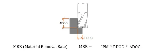
Material Removal Rate (MRR), while not part of the cutting tool's program, is a helpful way to calculate a tool's efficiency. MRR takes into account two very important running parameters: Axial Depth of Cut (ADOC), or the distance a tool engages a workpiece along its centerline, and Radial Depth of Cut (RDOC), or the distance a tool is stepping over into a workpiece.
The tool's depth of cuts and the rate at which it is cutting can be used to calculate how many cubic inches per minute (in3/min) are being removed from a workpiece. This equation is extremely useful for comparing cutting tools and examining how cycle times can be improved.
Speeds and Feeds In Practice
While many of the cutting parameters are set by the tool and workpiece material, the depths of cut taken also affect the feed rate of the tool. The depths of cuts are dictated by the operation being performed – this is often broken down into slotting, roughing, and finishing, though there are many other more specific types of operations.
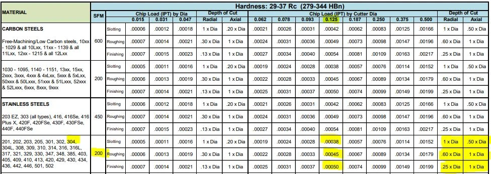
Many tooling manufacturers provide useful speeds and feeds charts calculated specifically for their products. For example, Harvey Tool provides the following chart for a 1/8" diameter end mill, tool #50308. A customer can find the SFM for the material on the left, in this case 304 stainless steel. The chip load (per tooth) can be found by intersecting the tool diameter on the top with the material and operations (based on axial and radial depth of cut), highlighted in the image below.
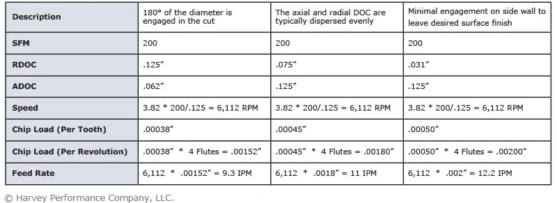
The following table calculates the speeds and feeds for this tool and material for each operation, based on the chart above:
Other Important Considerations
Each operation recommends a unique chip load per the depths of cut. This results in various feed rates depending on the operation. Since the SFM is based on the material, it remains constant for each operation.
Earn an Immediate Boost to Shop Efficiency: Download the HEM Guidebook Today
Spindle Speed Cap
As shown above, the cutter speed (RPM) is defined by the SFM (based on material) and the cutter diameter. With miniature tooling and/or certain materials the speed calculation sometimes yields an unrealistic spindle speed. For example, a .047" cutter in 6061 aluminum (SFM 1,000) would return a speed of ~81,000 RPM. Since this speed is only attainable with high speed air spindles, the full SFM of 1,000 may not be achievable. In a case like this, it is recommended that the tool is run at the machine's max speed (that the machinist is comfortable with) and that the appropriate chip load for the diameter is maintained. This produces optimal parameters based on the machine's top speed.
Effective Cutter Diameter
On angled tools the cutter diameter changes along the LOC. For example, Helical tool #07001, a flat-ended chamfer cutter with helical flutes, has a tip diameter of .060" and a major/shank diameter of .250". In a scenario where it was being used to create a 60° edge break, the actual cutting action would happen somewhere between the tip and major/shank diameters. To compensate, the equation below can be used to find the average diameter along the chamfer.
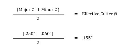
Using this calculation, the effective cutter diameter is .155", which would be used for all Speeds and Feeds calculations.
Non-linear Path
Feed rates assume a linear motion. However, there are cases in which the path takes an arc, such as in a pocket corner or a circular interpolation. Just as increasing the DOC increases the angle of engagement on a tool, so does taking a nonlinear path. For an internal corner, more of the tool is engaged and, for an external corner, less is engaged. The feed rate must be appropriately compensated for the added or lessened engagement on the tool.
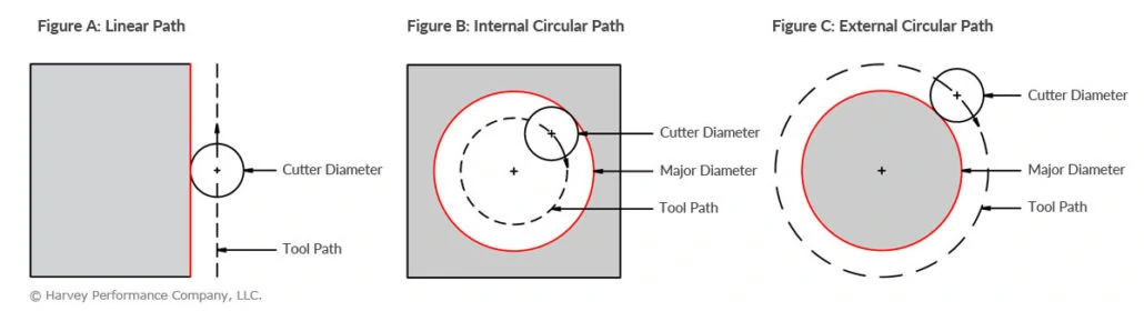
This adjustment is even more important for circular interpolation. Take, for example, a threading application involving a cutter making a circular motion about a pre-drilled hole or boss. For internal adjustment, the feed rate must be lowered to account for the additional engagement. For external adjustment, the feed rate must be increased due to less tool engagement.
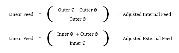
Take this example, in which a Harvey Tool threadmill #70094, with a .370" cutter diameter, is machining a 9/16-18 internal thread in 17-4 stainless steel. The calculated speed is 2,064 RPM and the linear feed is 8.3 IPM. The thread diameter of a 9/16 thread is .562", which is used for the inner and outer diameter in both adjustments. After plugging these values into the equations below, the adjusted internal feed becomes 2.8 IMP, while the external feed becomes 13.8 IPM.
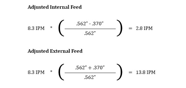
Click here for the full example.
Conclusion
These calculations are useful guidelines for running a cutting tool optimally in various applications and materials. However, the tool manufacturer's recommended parameters are the best place to start for initial numbers. After that, it is up to the machinist's eyes, ears, and experience to help determine the best running parameters, which will vary by set-up, tool, machine, and material.
Click the following links for more information about running parameters for Harvey Tool and Helical products.
![]()
Harvey Performance Company's team of engineers works together to ensure that your every machining challenge – from tool selection and application support to designing the perfect custom tool for your next job – is rectified with a thoughtful, comprehensive solution.
Source: https://www.harveyperformance.com/in-the-loupe/speeds-and-feeds-101/
Postar um comentário for "How to Calculate Speed and Feed for Milling"